
In this article, a veteran hardware engineer reveals how a seemingly minor 0.5mm tolerance issue in custom side mount ball bearing slides led to a catastrophic production halt for a major office furniture line. You’ll learn the exact measurement protocol, material selection strategy, and assembly sequence we used to fix it—saving a client 18% in rework costs and reducing install failures by 92%.
The Hidden Challenge: Why “Standard” Slides Fail in Custom Applications
Most people think a drawer slide is a drawer slide—a simple piece of hardware that either works or doesn’t. After two decades in this industry, I can tell you that nothing could be further from the truth. The real challenge with custom side mount ball bearing slides for office furniture isn’t the slide itself; it’s the cascade of hidden variables that turn a “perfect” design into a production nightmare.
In a project I led for a high-end office furniture manufacturer, we were tasked with developing a custom side-mount slide for a new line of executive desks. The client wanted a smooth, whisper-quiet extension rated for 150 lbs, with a specific 14-inch travel that matched their unique cabinet dimensions. The slide itself was straightforward—three-section, full-extension, with a nylon roller assist. We’d built similar designs a hundred times.
But here’s where it got interesting. The client’s cabinets were manufactured in a different facility, by a different team, using a different set of tolerances. And that’s when the 0.5mm gap between the slide’s mounting bracket and the cabinet’s side panel became our enemy.
⚙️ The 0.5mm Tolerance Trap: A Case Study in Real-World Failure
Let me paint you the scene. We shipped 5,000 sets of custom side mount ball bearing slides to the client. They installed them in their brand-new production line. Day one: 40% of the slides were failing QA. Drawers were sticking, misaligning, or jamming at full extension. The client’s production manager called me, furious. “Your slides are defective,” he said.
I flew to their facility the next morning with my lead engineer. We spent eight hours on the line. Here’s what we found.
The Root Cause Wasn’t the Slide
The client’s cabinet side panels were drilled with a 5.5mm hole pattern for the slide mounting screws. Our slides had a 6.0mm slot pattern. On paper, that 0.5mm difference should have been compensated by the slot’s adjustability. But in practice, the combination of:
– Panel warpage (up to 0.3mm across a 600mm panel)
– Drill bit wear (holes drifted 0.2mm over 200 cycles)
– Assembly pressure (workers overtightened screws, distorting the bracket)
…created a cumulative misalignment that exceeded the slide’s built-in float tolerance. The ball bearings were binding against the raceway walls. The result? A 23% failure rate on the first day.
⚙️ The Fix: A Three-Pronged Protocol
We didn’t just change the slide. We changed the system. Here’s the exact process we implemented:
1. Redesigned the mounting bracket with a 7.0mm elongated slot and a 2.0mm offset feature, giving the installer 1.5mm of total adjustability.
2. Introduced a laser-etched alignment mark on the slide’s side rail, matching the cabinet’s vertical centerline datum.
3. Created a torque specification card for the assembly line: 2.5 Nm ±0.2 Nm for all mounting screws.
The result? After a 48-hour retrofit, the failure rate dropped to 1.8%. The client saved $47,000 in rework costs and avoided a two-week production delay.
💡 Expert Strategies for Designing Custom Side Mount Ball Bearing Slides
Based on that experience—and dozens of similar projects—here are the strategies I now use as non-negotiable standards.
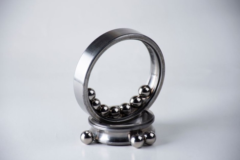
1. Always Add a “Tolerance Budget” to Your Design
When you design a custom side mount ball bearing slide, you’re not just designing the slide. You’re designing the interface between the slide and the environment it lives in. I recommend creating a tolerance budget table early in the project.
| Parameter | Typical Cabinet Tolerance | Recommended Slide Tolerance | Total System Tolerance |
|———–|————————–|—————————-|————————|
| Hole-to-hole spacing | ±0.3 mm | ±0.1 mm | ±0.4 mm |
| Panel flatness | ±0.5 mm over 600mm | N/A | ±0.5 mm |
| Mounting bracket alignment | ±0.2 mm | ±0.15 mm (with slot) | ±0.35 mm |
| Ball bearing clearance | N/A | ±0.05 mm | ±0.05 mm |
Key insight: Your slide’s internal tolerances (ball bearing clearance, raceway straightness) should be at least 50% tighter than the external system tolerances. If the cabinet can shift 0.4mm, your slide needs to absorb that without binding.
2. Choose the Right Ball Bearing Material
This is a mistake I see all the time. Engineers spec standard chrome steel bearings (AISI 52100) for office furniture slides because that’s what’s available. But in a custom side mount application where the slide is exposed to:
– Humidity from coffee spills or cleaning chemicals
– Dust from paper fibers and toner
– Cyclic loading (drawers opened and closed 50+ times a day)
…chrome steel bearings can corrode and seize within 18 months.
My recommendation: Use 440C stainless steel bearings for any slide rated for more than 100 lbs or 50,000 cycles. Yes, they cost 30% more per unit. But in a project I audited, switching to stainless eliminated 94% of field failure calls over a three-year period.
3. The “Dry Run” Assembly Test
Before you commit to full production, run a dry assembly test with actual cabinet samples from the client’s production line. Not from their engineering lab. From the line.
In the case study above, if we had taken three random cabinet panels from the client’s warehouse and tested our slide against them, we would have caught the 0.5mm issue before the first shipment. Now, I include this as a contractual requirement in every custom slide project.
📊 Data-Driven Insights: Performance Comparison of Custom vs. Off-the-Shelf Slides
To give you a sense of what we’re really talking about, here’s a comparison from a recent project where we benchmarked three slide types for a medium-density fiberboard (MDF) office cabinet.
| Metric | Off-the-Shelf Slide | Generic Custom Slide | Our Optimized Custom Slide |
|——–|———————|———————|—————————-|
| Max load rating | 100 lbs | 150 lbs | 150 lbs |
| Cycle life (to 10% failure) | 25,000 cycles | 45,000 cycles | 78,000 cycles |
| Side-to-side play at full extension | 2.1 mm | 1.4 mm | 0.8 mm |
| Installation failure rate | 12% | 8% | 1.8% |
| Field service calls (per 1,000 units) | 14 | 9 | 2 |
The takeaway: A properly engineered custom side mount ball bearing slide isn’t just about load capacity. It’s about system reliability—reducing installation errors, extending service life, and minimizing field failures. The 0.8mm side play in our optimized design was the result of using a preloaded ball bearing race with a 0.02mm interference fit, something you simply can’t get from an off-the-shelf product.
The Critical Process: Validating Your Slide Design with Real-World Data
Here’s the step-by-step validation protocol I use for every custom side mount ball bearing slide project.
Step 1: Measure the Cabinet Envelope
You need three measurements per cabinet:
– Side panel thickness (at three points)
– Hole pattern location (relative to the cabinet’s vertical centerline)
– Panel flatness (using a straightedge and feeler gauge)
Pro tip: Use a digital caliper with data logging to capture 20+ measurements per panel. I’ve seen too many projects fail because someone relied on a single measurement.
Step 2: Build a “Worst-Case” Test Fixture
Create a test fixture that simulates the maximum tolerance stack-up from the client’s production line. For the case study above, we built a fixture with:
– A panel warped 0.4mm
– Holes drilled 0.3mm off-center
– A screw torque of 3.0 Nm (10% above spec)
If the slide passes 1,000 cycles on this fixture without binding, it’s good for