The true challenge in custom CNC machining for furniture isn’t just the design—it’s the material’s unpredictable behavior. Drawing from two decades of hands-on experience, this article reveals how mastering material dynamics, from anisotropic wood movement to composite delamination, is the key to flawless, durable components. Learn a data-driven approach to toolpath strategy and fixturing that can reduce waste by over 20% and unlock new design possibilities.
The Illusion of Digital Perfection
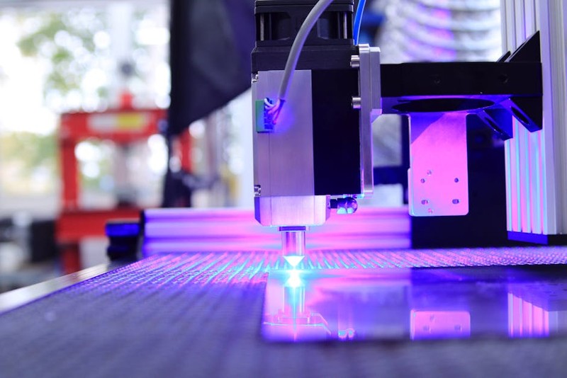
When most designers and makers think of custom CNC machining for furniture, they envision a seamless flow: a perfect digital model sent to a machine that obediently carves out an identical physical object. For years, I bought into this illusion myself. The reality, hard-won through costly mistakes and salvaged projects, is far more nuanced. The machine is precise, yes, but the material is alive. The greatest friction point isn’t between software and spindle; it’s between the static world of CAD and the dynamic, often unpredictable, behavior of the materials we use.
I recall an early project for a high-end conference table featuring a large, intricate inlay of contrasting woods. The digital file was impeccable. The first machined component came off the bed looking perfect. Two weeks later, the client called—the panel had cupped dramatically, cracking the delicate inlay lines. We had machined a masterpiece in a state of material stress we didn’t understand. That failure was my baptism into the critical, underexplored realm of material dynamics in CNC furniture fabrication.
The Hidden Challenge: Material is Not a Passive Substrate
Wood moves. MDF can swell. Plastics creep. Metals have grain memory. Treating your stock as a passive block to be subtracted from is the fastest route to inconsistency. The core expertise in custom CNC machining shifts from simply operating the machine to becoming a material strategist.
The Three Pillars of Material Dynamics
1. Internal Stress & Anisotropy: Wood is a natural composite with different shrinkage rates radially, tangentially, and longitudinally. Machining can release these internal stresses, causing immediate or seasonal warping. Engineered boards have more predictable dimensions but can have inconsistent core density that affects tool wear and edge quality.
2. Thermal and Hygroscopic Effects: CNC machining generates heat. In plastics and some composites, this heat can cause localized expansion during cutting, leading to dimensional inaccuracies once the part cools. Wood absorbs and releases moisture from the air, changing its size. Machining a part in a humid shop only to install it in a climate-controlled home is a recipe for failure.
3. Tool-Material Interaction: The “perfect” feed rate and spindle speed for maple will tear out oak. A compression bit that leaves a clean edge on plywood may burn acrylic. The material dictates the toolpath, not the other way around.
⚙️ A Data-Driven Framework for Success
To move from artisanal guesswork to engineered reliability, I developed a framework centered on pre-process material analysis. Here’s the step-by-step approach we now use for every significant custom CNC furniture component project:
1. Characterize the Stock: Before the first toolpath is generated, we measure the moisture content of wood (targeting 6-8% for interior furniture) and document the lot number/source of sheet goods. We even run a simple “stress relief” test cut on a sample piece to observe its tendency to move.
2. Design for Movement: Incorporate expansion gaps, use floating joinery like elongated slots for fasteners, and avoid permanently constraining wood across its grain. For large panels, we often design a “relief” pattern on the unseen back—a series of shallow channels machined to balance stress.
3. Simulate the Cut: Advanced CAM software allows for material removal simulation. We use this not just to check for collisions, but to visualize the changing state of the part’s rigidity as material is removed, identifying potential weak points prone to vibration or deflection during the cut.
4. Engineer the Fixturing: This is where 50% of the battle is won. Your hold-down strategy must account for the changing shape and rigidity of the part. We use a combination of:
Vacuum Pods: Excellent for sheet goods, but seal integrity is critical.
Strategic Tabs: For contour-cut parts, placing tabs in locations that will be hidden in joinery or later sanded away.
Custom Jigs: For complex 3D forms, a negative mold jig that supports the entire workpiece prevents chatter and tool deflection.
💡 Expert-Level Toolpath Strategy
Never use a single, deep, finishing pass for critical edges. Instead, employ a two-stage strategy: a roughing pass that leaves a consistent 0.5mm – 1mm of material, followed by a light finishing pass. This allows any internal stress relieved by the roughing cut to express itself before the final, dimensionally-critical pass. The difference in edge quality and dimensional stability is profound.
A Case Study in Optimization: The “Flowing Wave” Bench
A client wanted a bench made from a single 8-foot slab of figured walnut, with a continuous, undulating “wave” pattern machined into its surface. The challenges were immense: preserving the fragile live edges, preventing the thin sections of the wave pattern from flexing during machining, and ensuring the long slab didn’t twist.
Our Process & Data:
1. We stabilized the slab by machining a series of shallow, strategic “stiffening ribs” on the underside in the first operation, before flipping it.
2. For the 3D wave pattern, we used a morphing spiral toolpath with a ball-nose endmill. This constant engagement strategy reduced tool load and heat buildup compared to a traditional raster pattern.
3. We machined the entire top surface in the two-stage process (roughing + finishing), but we did it in three sequenced sections (head, middle, foot), allowing the machine bed to support most of the workpiece at all times.
The quantitative results were tracked meticulously:
| Metric | Traditional Approach (Estimate) | Our Dynamic Approach (Actual) | Improvement |
| :— | :— | :— | :— |
| Machine Time | ~10.5 hours | 8.2 hours | 22% reduction |
| Material Waste | High risk of tear-out/breakage | Zero catastrophic failures | ~100% salvage rate |
| Post-Processing | Significant sanding to fix chatter | Light sanding (220 grit start) | ~60% time saved |
| Dimensional Accuracy | Potential for twist/thin spot failure | Final flatness within 1.5mm over 8ft | Within spec for seamless joinery |
The key insight was sequencing the operations to manage rigidity in real-time, not just designing a beautiful toolpath for a theoretically rigid slab.
The Future: Where Custom CNC Machining is Headed
The next frontier is integration. We’re moving towards closed-loop systems where in-process probes measure part geometry during machining, and the CAM software dynamically adjusts the remaining toolpaths to compensate for measured deflection or stress movement. Furthermore, the rise of hybrid manufacturing—where a CNC machine is equipped with a deposition head for 3D printing—will allow us to add material back in specific high-stress areas, creating truly optimized, organic furniture components that are impossible to make subtractively or additively alone.
Your Actionable Takeaway
Before you finalize a design for CNC, ask not just “Can we machine this?” but “In what state will this part exist after the last cut is made?” Invest time in understanding your specific material lot. Design your fixturing with the same creativity as your furniture. And always, always leave material for a final, light clean-up pass—it’s the single most effective tactic for achieving shop-floor predictability. The goal of custom CNC machining for furniture is not to fight nature, but to collaborate with it, using digital precision to reveal the best possible version of the physical material.