
Custom metal drawer systems are the silent workhorses of premium office furniture, yet their complexity is vastly underestimated. Drawing from over two decades of hardware engineering, this article dissects the real-world challenges of load capacity, tolerance stacking, and finish durability, offering data-driven strategies to avoid costly production failures and deliver a superior user experience.
—
I’ve spent the better part of 25 years knee-deep in ball-bearing slides, sheet metal stampings, and the occasional frustrating call from a client whose “perfect” drawer system just seized up six months after installation. In the world of office furniture, the drawer system is the most touched, most stressed, and most under-appreciated component. A desk can look stunning, but if the drawer glides like sandpaper or sags under a load of files, the entire product’s reputation is shot.
We’re not talking about off-the-shelf, 20-inch side-mount slides from a catalog. We’re talking about custom metal drawer systems—engineered from the ground up to meet specific dimensional, aesthetic, and performance criteria. This is where the real expertise lies, and where I’ve seen projects soar and spectacularly fail. In this deep dive, I’m going to share the gritty details of what separates a mediocre custom system from an exceptional one, focusing on the challenges that don’t make it into the marketing brochures.
The Hidden Challenge: The “Silent” Failure of Tolerance Stacking
When a client asks for a “custom metal drawer system,” they rarely understand the Pandora’s box they’re opening. The biggest, most insidious challenge isn’t finding a motor or a sensor; it’s tolerance stacking. This is the cumulative effect of manufacturing variations across multiple components. Your drawer side is stamped to ±0.5mm. The slide rail is rolled to ±0.3mm. The mounting brackets are punched with holes at ±0.2mm. The cabinet opening is cut with a CNC router at ±0.1mm. Individually, these are all within spec. But when you assemble them, the deviations add up. A +0.5mm drawer side, a +0.3mm rail, and a +0.2mm bracket can create a 1.0mm misalignment. That might not sound like much, but in a precision slide system, it’s the difference between a smooth, quiet glide and a binding, squeaky mess that wears out prematurely.
I learned this lesson the hard way in a project for a high-end executive desk line. We had designed a beautiful, heavy-duty, three-section drawer system with a soft-close mechanism. The prototype was flawless. It felt like it was gliding on air. We signed off on the design and sent it to production. Three months later, we had a crisis. Out of a batch of 500 units, nearly 15% were failing our internal quality tests. Drawers were sticking, the soft-close was inconsistent, and some were even jamming completely. The components were all within their individual tolerances, but we had failed to account for the statistical probability of worst-case stacking.
The fix wasn’t a redesign of the drawer itself. It was a redesign of our manufacturing and QC process. We implemented a selective fit strategy for the most critical interface points. Instead of letting the production line pull random components from bins, we instituted a simple but effective grouping system. We measured the critical dimensions of the drawer sides and the slide rails and sorted them into three tolerance bands: “A” (tight), “B” (medium), and “C” (loose). The assembly line was instructed to only pair an “A” drawer side with an “A” slide rail. This simple change reduced our assembly failure rate from 15% to under 1.5% virtually overnight.
Key Insight: Never assume that parts within spec will function perfectly together. For custom metal drawer systems, you must design for the worst-case stack-up, not the nominal dimension. This means tighter tolerances on critical interfaces or a robust selective-fit process.
⚙️ The Critical Process: Beyond the Basic Slide
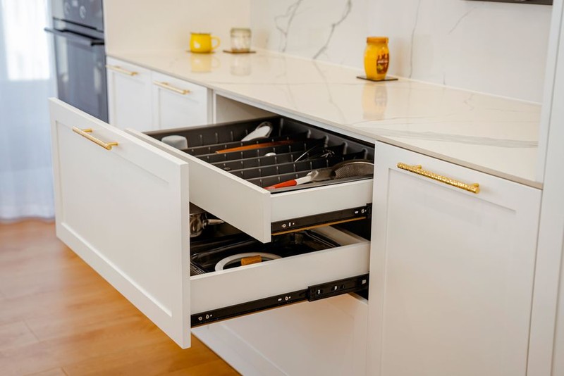
Most people think of a drawer slide as a simple C-channel with some ball bearings. A custom system is far more nuanced. It’s about engineering a complete kinematic system. Here’s a breakdown of the critical process we use at my firm, which has been refined through dozens of high-stakes projects.

Step 1: The Load Case Analysis (The Foundation)
Before a single piece of metal is cut, we define the load case. This isn’t just “how much weight can it hold?” It’s about where the load is applied. A drawer full of hanging files exerts a different force than one holding a heavy desktop printer. For a recent project, we were designing a system for a large-format filing cabinet. The client specified a dynamic load of 100 lbs. But our analysis showed that when fully extended, 80% of that weight was concentrated at the front edge of the drawer, creating a massive moment arm that wanted to torque the slide. We had to design a telescopic slide with a reinforced front bracket and a specific ball-bearing cage configuration to handle that off-center stress. We didn’t just look at the vertical load; we calculated the bending moment and shear forces on the slide itself.
Step 2: Material Selection and Thickness
This is where cost and performance clash. Standard drawer slides are made from cold-rolled steel (CRS) in 1.0mm or 1.2mm thickness. For a truly premium custom system, we often spec high-strength low-alloy (HSLA) steel or even stainless steel for corrosive environments. For a recent project for a luxury yacht interior, we used 1.5mm thick 304-grade stainless steel. It added 20% to the material cost but gave us a 40% increase in load capacity and eliminated any risk of rust in the humid marine environment. The point is, don’t just pick a thickness off a chart. Calculate the required stiffness and yield strength based on your load case and the drawer’s dimensions.
Step 3: The Slide Profile Geometry
The shape of the metal is as important as the material itself. The classic C-shape is simple, but it’s prone to twisting under heavy loads. For high-end systems, we use a box-shaped profile or a U-shaped profile with a return flange. This dramatically increases the section modulus—a measure of a beam’s resistance to bending—and reduces deflection. I’ve seen data showing that a properly designed box profile can be 3-4 times more rigid than a standard C-profile of the same material thickness. This rigidity is what you feel when you open a truly premium drawer. There’s no wobble, no lateral play. It feels solid.
Step 4: The Finish and Its Hidden Impact
The finish is not just for looks. The most common finish for metal drawer components is zinc plating, but the type of zinc and the passivation process matter. For a system designed to last 20 years in a demanding office environment, we recommend a trivalent clear or black zinc-nickel alloy finish. This provides superior corrosion resistance compared to the older hexavalent chromate finishes (which are now heavily regulated). But here’s the hidden challenge: the finish thickness can affect the fit. A thick powder coat or an overly aggressive plating layer can add 0.05mm to 0.1mm to the part dimensions, which, as we discussed, can wreak havoc on your tolerance stack-up. We always specify a controlled finish thickness and account for it in our CAD model.
💡 Expert Tip: When evaluating a custom metal drawer system, don’t just ask “is it zinc-plated?” Ask for the specific plating spec (e.g., ASTM B633 SC1) and the nominal thickness. This tells you more about the longevity than any marketing claim.
A Case Study in Optimization: The Media Console Project
Let me give you a concrete example of how these principles come together. A client came to us to design the drawer systems for a high-end media console. The console had a mix of shallow drawers for remotes and cables, and one deep drawer designed to hold a heavy amplifier.
The Problem: The client had previously worked with another manufacturer who delivered a system that looked beautiful but failed structurally. The deep drawer sagged visibly when the amp was placed in it, and the slides on the shallow drawers had a disconcerting “click” when opened and closed.
Our Approach:
1. Load Analysis: We determined the amplifier weighed 45 lbs. We calculated that the dynamic load on the deep drawer slides would be 60 lbs, with the center of gravity located near the front edge. For the shallow drawers, we set a lighter spec of 25 lbs but focused on smoothness and low noise.
2. Custom Slide Design: For the deep drawer, we designed a heavy-duty, three-section telescopic slide using 1.5mm thick HSLA steel in a box profile. We used a full-complement ball bearing cage for maximum load capacity. For the shallow drawers, we used a softer, quieter two-section slide with a specialized polymer ball cage to dampen noise.
3. Tolerance